Designing Antenna Systems for Maximum Sensitivity
Notable Patents on Antenna Design
Designing Antenna Systems for Maximum Sensitivity
Communications Link Quality
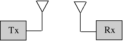
The design of an antenna system involves deciding how much antenna gain is needed and specifying amplifiers and receivers for a specific signal-to-noise ratio. For a given power density, the gain of the antenna determines the power into the receiver. Our job is to choose the antenna gain for acceptable performance. If the antenna gain is too little, then the signal will be noisy. If it is too large, the signal will be distorted due to saturation of the receiver.
When you listen to a radio and the signal is weak you hear noise. This audio noise is caused by electromagnetic noise from the random fluctuation of electrons. Some of this noise comes from outside the antenna system (external noise) and some from inside the receiving system (internal noise). The quality of the received signal depends on the ratio of signal power to noise power, called signal-to-noise ratio, or SNR.
In this tutorial we will learn how to calculate compression points, SNR, sensitivity, and minimum discernible signal levels. This will enable us to predict receiving system performance and ultimately design the system for maximum sensitivity.
In a communications link, if the signal is too noisy we could increase the transmitter power, the transmit or receive antenna gains, or decrease the noise added by the receive system. In other words, the signal-to-noise ratio out of the receiver can be improved by increasing the signal power at the input to the receiver or by decreasing the noise added by the receive system. First we will learn how to quantify the noise added by the system and then how to calculate the signal-to-noise ratio.
In the diagram above, for a given power density, the gain of the receive antenna determines the signal power into the receiver. We need to choose the receive antenna gain for acceptable performance. If the gain is too little, then the signal will be noisy. If it is too large, the signal will be distorted due to saturation of the receiver.
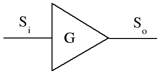
Definition: Amplifier gain is the ratio of the component's or system's signal output power to its signal input power.
G[dB] = 10log(So / Si) = So[dBm] - Si[dBm]
Compression Point
The 1dB compression point tells us the largest signal the receiver, amplifier, or system can handle without significant distortion. The 1 dB compression point refers to the input or output that results in 1dB of gain compression. This compression causes saturation distortion.
Example: An amplifier, whose input and output power are shown in the diagram below, normally has 30 dB of gain. When it is at the 1 dB compression point it only has 29 dB of gain and its output is distorted.
The compression point can be referenced to the input or the output. For receivers or systems, the maximum output is usually specified. The variables CPi and CPo will be used to refer to input and output referenced compression points, respectively. In the previous example
CPi = -30 dBm
CPo = -1 dBm
Example: What is the input compression point for this amplifier?

Solution: 19 dB is the amplifier gain when it is in 1 dB of gain compression and therefore
CPi = CPo[dBm] - 19dB = -14dBm
An antenna system has a receiver, transmission line, and usually one or more amplifiers. The receiver and amplifiers all have their separate compression points. Only the compression point of one of the components will end up being the determining factor for the compression point of the system.
Example: What is the system 1 dB compression point (referenced to the input) for the antenna system shown below?

Solution: In this case, as the power level into the system is increased the first component to go into compression is the receiver. The input, when the receiver is at its 1 dB compression point, is
Pi = 0dBm - 20dB = -20dBm
Therefore the system compression point (referenced to its input) is -20 dBm.
Example: What is the system 1 dB compression point (referenced to the input) for the antenna system shown below?
Solution: This time the transmission line has 8 dB of attenuation. We need to determine which component saturates first, the amplifier or the receiver. When the amplifier output is at its compression point of 5 dBm, the receiver input is 8 dB less, or -3 dBm. So the preamp compresses before the receiver and the system 1 dB compression point (referenced to the input) is
CPi = 5dBm - 19dB = -14dBm
Noise Figure
We first studied compression points in order to determine the maximum signal that a receiving system can handle. Next we examine noise in order to understand the minimum signal power that a system can detect. The noise produced by something is generally proportional to its absolute temperature. Absolute temperature is measured in units of Kelvin.Converting between Kelvin, Celsius, and Fahrenheit is through the following formulas:
oK = 273 + oC
oC = (oF - 32)(5 / 9)
The noise delivered from a resistor to a matched load is equal to:
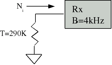
Ni = kTB
where Ni is in watts, T is the temperature of the resistor in Kelvin, B is the bandwidth in Hertz, and k=1.38x10⁻²³ is Boltzman's constant.
Exercise: What is the noise power delivered to this receiver?
Definition: The noise temperature of an antenna is the temperature Ta, such that the noise coming out of the terminals of the antenna is kTaB. The antenna noise temperature is a function of the temperature of the matter in the direction the antenna is pointed in, its antenna pattern, the frequency, and the radiation efficiency of the antenna.
At microwave frequencies, for antennas whose takeoff angle is approximately zero degrees elevation, the half of the antenna's field of view includes the earth and the other half the sky. The temperature of the earth is about 290 Kelvin, but it only occupies half of the beamwidth. The result is that the antenna noise temperature Ta is approximately 150K. Earth station antennas see lower temperatures because they look up into the cold sky. HF antennas have a high antenna noise temperature due to HF atmospheric noise generated mostly by lightning storms around the world.
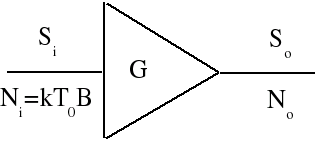
Definition: The noise figure is a way of describing the amount of noise generated in a receiver, amp, transmission line, antenna system, or other component. The noise figure of a component or system is defined as the signal-to-noise ratio at the input divided by the signal-to-noise ratio at the output, with the input noise equal to the noise available from a matched resistance at a temperature of T0=290 Kelvin.
F = (Si / Ni)/(So / No) where Ni = kT0B
F[dB] = 10logF
The term noise factor is often used to describe the linear form of noise figure. In other words the ratio of input to output SNR is described as the noise factor and noise figure is the noise factor measured in dB.
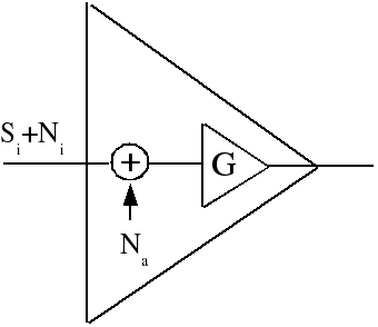
The higher the noise figure (or noise temperature) of a component or system, the more noise it adds to the signal. For this reason, it is desirable to have low noise figure (or noise temperature) components and systems. Noise figures (or noise temperatures) of receivers and amplifiers are specified in manufacturers' datasheets. Noise figures can also be measured with a noise figure meter. A component generates noise internally, which degrades the SNR of the signal passing through it by adding noise to the signal. A component can be modeled as a noise-free amplifier of gain G, with noise added to the signal in a summing junction preceding the perfect amp, as shown below.
Noise temperature is related to noise figure as follows:
F[dB] = 10log(1 + T/T0)
T = (F - 1)T0
System Sensitivity
Definition: The minimum discernible signal (MDS) is the input that gives an output signal-to-noise ratio of 0 dB (where the signal power is equal to the noise power).
MDS[watts] = kT0BF
where F is the noise figure of the component or system. In dB this is
MDS[dB] = 10log(kT0) + 10logB + F[dB]
MDS[dBm] = -174 + 10logB + F[dB]
Alternatively, in terms of noise temperature
MDS[watts] = kTB
where T is the noise temperature of the component or system in Kelvin. In dB this would be
MDS[dBm] = -199 + 10logT + 10logB
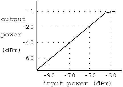
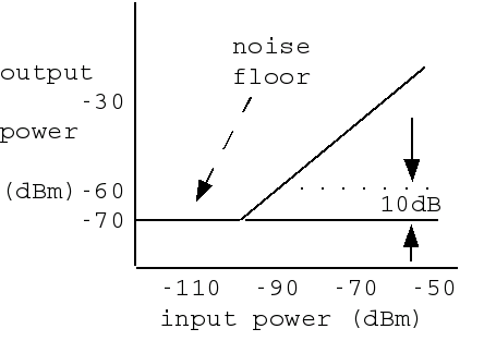
Definition: The sensitivity is the smallest signal we can put in to get a specified minimum SNR out of the system or component. The noise generated inside the system or component is what limits the sensitivity. The graph below shows the response of a receiver whose sensitivity (for 10 dB SNR) is -90 dBm.
The broader the bandwidth of the receiver, the more noise it passes to its output, so sensitivity is bandwidth-dependent. The relationship between sensitivity and noise figure is
Seinsitivity[dBm] = MDS[dBm] + (S/N)min[dB]
It is usually desirable to operate the receiver at some distance away from the antenna, so a transmission line is needed. This will degrade the sensitivity of the system as a whole. The loss in the transmission line is equivalent to its noise figure and can be lumped in with the receiver noise figure rather than being considered separately:
F[dB] = Ao[dB] + Frx[dB]
This degrades the system sensitivity and increases the antenna gain needed. A preamp will reduce the noise figure of the system if its noise figure is low enough and if the gain is correctly chosen. This will reduce the system sensitivity and allow us to use a lower gain antenna or give us a better SNR using the same antenna.

The noise figure of a cascaded system (which includes amps, transmission lines, and the receiver) is a function of the noise figures and gains of the individual components, and can be derived from the noise figure definition to be
Fsys = F1 + (F2-1)/G1 + (F3-1)/(G1G2) +...+ (Fn-1)/(G1G2...Gn-1)
where F1 and G1 are the (linear) noise figure and gain of the first component (the one furthest from the receiver) and the nth component is the receiver.
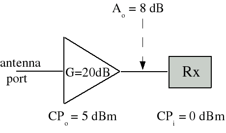
Example: What is the noise figure (in dB) of the following system?
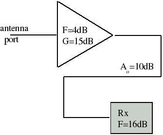
Solution: First we convert all of the noise figures and gains into linear values.
F1 = 104/10 = 2.51
G1 = 1015/10 = 31.6
F2[dB] = Ao[dB] + Frx[dB] = 26 dB
F2[dB] = 1026/10 = 398
Fsys = F1 + (F2-1)/G1 = 15.1
Fsys = 11.8 dB
Designing for Maximum Sensitivity
It is apparent from the system noise figure equation that if the gains are large enough, then all terms will be insignificant in comparison with the first term. Therefore the system noise figure will be approximately equal to the noise figure of the first component. Fsys = F1 is approximately correct as long as (F2-1)/G1 << F1 and (F3-1)/(G1G2) << F1 etc. If we ignore the -1 in the numerator and convert the first condition to dB, then it becomes
F2[dB] - G1[dB] << F1[dB]
As a rule of thumb, 10 dB is usually taken as equivalent to "much much greater than," so
G1[dB] = 10 + F2 - F1[dB]
A similar process for the second condition results in
G2[dB] = 10 + F3[dB] - F1[dB] - G1[dB]
The 10 dB factor is called the excess gain of the amplifier. The strategy of choosing amplifier gains large enough to make the system noise figure approximately equal to the noise figure of the preamp (the amplifier closest to the antenna) is called designing for maximum sensitivity. This strategy will allow the system to detect the weakest possible signal.
Copyright © 2005-2015 Amp Books LLC All Rights Reserved
Notable Patents on Antenna Design
Zeppelin Antenna
German Patent Number: 225204
Year: 1909
Inventor: Hans Beggerow
Original Document: German Patent Number 225204
Year: 1909
Inventor: Hans Beggerow
Original Document: German Patent Number 225204
Claim (translated from the original German): Airborne wiring diagram, marked by two dangling wires of unequal length, which in the vicinity of the airship form a Lecher system.

Beverage Antenna
US Patent Number: 1381089
Year: 1920
Inventor: Harold H. Beverage
Original Document: US Patent Number 1381089
Year: 1920
Inventor: Harold H. Beverage
Original Document: US Patent Number 1381089
Excerpt: In carrying my invention into effect I make use of a horizontal preferably aperiodic antenna extending in a direction parallel to the direction of transmission of the signals to be received. This antenna is constructed with distributed capacity inductance and resistance of such values that the currents produced therein by the desired signals increase progressively from the end of the antenna nearest the transmitting station becoming in the preferred case, the maximum at the end farthest from the transmitting station.

Franklin Antenna
British Patent Number: 242342
Year: 1924
Inventor: Charles Samuel Franklin
Original Document: British Patent Number 242342
Year: 1924
Inventor: Charles Samuel Franklin
Original Document: British Patent Number 242342
Abstract: In order to secure a pronounced directional effect from aerials of the type that are electrically long in comparison with the signal wavelength, provision is made for suppressing radiation from every alternate half wavelength of the stationary-wave formation along the aerial. Fig. 2 shows, for example the normal conditions existing along an aerial A one-and-a-half times the signal wavelength, the stationary- wave formation being shown by the curve B, whilst the polar diagram of radiation is illustrated by the six-point curve C. By doubling back on itself the central stationary-wave segment of the aerial, the resultant polar curve is altered to the form shown in Fig. 3. Alternatively, the doubled-back portion may be replaced by an electrical equivalent, such as an inductance coil with or without a parallel condenser, substantially tuned to the fundamental wavelength. The longer or higher the aerial, modified in this manner, the sharper is the directional effect. The invention may be applied to aerials of the type described in Specification 226,246.

Yagi-Uda Antenna
Japanese Patent Number: 69115
Year: 1926
Inventors: Hidetsugu Yagi and Shintaro Uda
Original Document: Japanese Patent Number 69115, page 1
Japanese Patent Number 69115, page 2
Year: 1926
Inventors: Hidetsugu Yagi and Shintaro Uda
Original Document: Japanese Patent Number 69115, page 1
Japanese Patent Number 69115, page 2
The Yagi antenna is an array of dipoles coupled by electric and magnetic fields. It was effectively used by the allies in World War II as a radar antenna and then saw widespread use throughout the world as a television receiving antenna. This remarkable structure allows the elements to be combined into a high-gain, unidirectional array without interconnecting feed lines. Each element is a continuous piece of metal without an insulator in the center, providing high strength and simple construction. The antenna also has very low weight and wind load compared to its gain. (My thanks to Harry Hsieh, a patent engineer in Taiwan, for obtaining the original patent document.)

Bruce Antenna
US Patent Number: 1813143
Year: 1927
Inventor: Edmond Bruce
Original Document: US Patent Number 1813143
Year: 1927
Inventor: Edmond Bruce
Original Document: US Patent Number 1813143
Excerpt: Because of the physical dimensions of the antenna, energy supplied thereto by a local source for radiation, or derived from a wave incident thereupon, produces in the active elements currents which are in phase with each other.

Sterba Antenna
US Patent Number: 1885151
Year: 1929
Inventor: Ernest J. Sterba
Original Document: US Patent Number 1885151
Year: 1929
Inventor: Ernest J. Sterba
Original Document: US Patent Number 1885151
Excerpt: It is one object of this invention to transmit or receive radio frequency waves with greater directivity in the earth's plane than heretofore practiced. It is another object of this invention to transmit or receive radio frequency waves in an extremely low-lying angle of projection. By means of the invention the above two objects may be achieved jointly so as to make possible a remarkably close approach to the theoretical ideal of point-to-point communication in which all the transmitted energy is utilized at the related receivers. It is still another object of this invention to transmit energy between the antenna elements and their associated translating apparatus with comparatively less energy loss and in a more simple and inexpensive manner than heretofore done.


Rhombic Antenna
US Patent Number: 2285565
Year: 1931
Inventor: Edmond Bruce
Original Document: US Patent Number 2285565
Year: 1931
Inventor: Edmond Bruce
Original Document: US Patent Number 2285565
Excerpt: An object of the invention is to render directive antennae capable of effective operation over a considerable range of wave lengths. Another object is to secure a relatively high angle of reception or emanation. An additional object of the invention is to enable an antenna to have a sharp selectivity. A further object is to economize in the cost of supporting structures as compared with that of previous antennae of similar directional characteristics. A still further object of the invention is to discriminate against undesired horizontally projected energy.

Turnstile Antenna
US Patent Number: 2086976
Year: 1935
Inventor: George H. Brown
Original Document: US Patent Number 2086976
Year: 1935
Inventor: George H. Brown
Original Document: US Patent Number 2086976
Excerpt: I am aware that vertical antenna systems of a height not exceeding a half wavelength may be used for horizontal radiation. Such systems are satisfactory for long wavelengths but are defective for short waves. It has been proposed to reverse phases between alternate half wave sections and thereby permit a plurality of half wavelength sections to be employed. An antenna system of several half wave sections offers practical difficulties in the matter of separately insulating the sections. It has also been proposed to employ horizontal antenna elements with insulated masts and phase adjusting circuits, but such systems offer serious structural and electrical difficulties. The novel arrangement which I propose may be used to overcome these difficulties and at the same time improve the radiating efficiency.


Folded Dipole Antenna
US Patent Number: 2283914
Year: 1937
Inventor: Philip S. Carter
Original Document: US Patent Number 2283914
Year: 1937
Inventor: Philip S. Carter
Original Document: US Patent Number 2283914
Excerpt: Although the dipole has a sufficiently broad tuning characteristic to give satisfactory transmission and reception over a band of frequencies such as may be used in television, it has been found that when this type of half wave antenna is matched to the transmission line in any of the known ordinary ways (as by the use of shunt impedance elements, or fanning and tapping of the transmission lines, or by the use of the quarter wave section of line) the tuning characteristic of the dipole is made very much narrower and is insufficient for the band of frequencies now generally used for television purposes. As a result of tests made on half wave dipoles, the conclusion was reached that the desired flat impedance versus frequency characteristic over a broad range must be obtained without the use of the usual impedance matching circuits between the antenna and the transmission line.


Coaxial Antenna
US Patent Number: 2184729
Year: 1937
Inventor: Arnold B. Bailey
Original Document: US Patent Number 2184729
Year: 1937
Inventor: Arnold B. Bailey
Original Document: US Patent Number 2184729
Excerpt: One object of this invention is to produce an undistorted radio field of maximum intensity. Another object of this invention is to eliminate radiation from a transmission line and other auxiliary apparatus associated with an antenna system. Still another object of this invention is to secure, in practice, an antenna directive characteristic which is the same as the corresponding theoretical characteristic. A further object of this invention is to prevent, in a coaxial line system, the establishment of currents on the outer surface of the sheath.


Butterfly Dipole Antenna
US Patent Number: 2175253
Year: 1938
Inventor: Philip S. Carter
Original Document: US Patent Number 2175253
Year: 1938
Inventor: Philip S. Carter
Original Document: US Patent Number 2175253
Excerpt: The present invention relates to a short wave antenna system and has for one of its objects to provide a simple form of short wave antenna which has an impedance versus frequency characteristic considerably wider than that of a simple dipole type of antenna.

Slot Antenna
British Patent Number: 515684
Year: 1938
Inventor: Alan Dower Blumlein
Original Document: British Patent Number 515684
Year: 1938
Inventor: Alan Dower Blumlein
Original Document: British Patent Number 515684
Abstract: A high-frequency transmission line, which also acts as a radiator, consists of a metal conducting tube 1, Fig. 1, of copper with a longitudinal slot 2. The tube forms a "channel for the transmission of magnetic flux," and is equivalent to a line having inductance in series, and shunted by elements of inductance and capacity in parallel. High-frequency signaling currents may be fed to the line by a coil 4, or by leads 4a connected across the slot, and are taken off by a coil 5. Flux leakage across the slot may be regulated by a plate 6, Fig. 2. Or the size of the slot may be adjusted, in order to tune the line to the working frequency, as shown in Figs. 3 and 5. The tube may be used as a transmitting aerial, giving maximum radiation at right-angles to its length, and comparatively little radiation axially. It is equivalent to a single-turn loop or frame, one wavelength long. The feed may be central or at one end. As shown in Fig. 6, the tube 7 is supported at voltage nodes 9 from a hollow mast 8, and is fed with signal energy at points 10, 11, half a wave length apart, from leads which are led up through the mast as shown in Fig. 7. A tube with a diameter of from six to twelve inches is suitable for transmitting a wavelength of 5 meters, though tubes of greater diameter, provided with more than one slot, may be used for covering a wide frequency-range.

Corner Reflector Antenna
US Patent Number: 2270314
Year: 1940
Inventor: John D. Kraus
Original Document: US Patent Number 2270314
Year: 1940
Inventor: John D. Kraus
Original Document: US Patent Number 2270314
Excerpt: The use of reflecting surfaces to direct the waves from or to an antenna is old.

Discone Antenna
US Patent Number: 2368663
Year: 1943
Inventor: Armig G. Kandoian
Original Document: US Patent Number 2368663
Year: 1943
Inventor: Armig G. Kandoian
Original Document: US Patent Number 2368663
Excerpt: In keeping with progress made during the last few years in the development of ultra-high frequency radio technique, and applications thereof to aircraft communication, direction finding, and so forth, it has become necessary to develop special antennas and antenna systems suitable for installation on such aircraft. Flying conditions are such that these antennas must necessarily be small and rigid in their construction and also offer a minimum of wind resistance, in order that the flying efficiency of the aircraft will be unimpaired. In accordance with my invention I have provided a small rigid antenna suitable for mounting on the surface of the fuselage or other component of the airplane structure and in certain embodiments I have also provided a streamlined protecting shield or housing covering or so cooperating with the construction of the antenna system as to greatly reduce wind resistance. This housing preferably takes the form of a "blister" which is only slightly elevated from the normal surface of the aircraft on which it may be installed.

Batwing Super-Turnstile Antenna
US Patent Number: 2480153
Year: 1945
Inventor: Robert W. Masters
Original Document: US Patent Number 2480153
Year: 1945
Inventor: Robert W. Masters
Original Document: US Patent Number 2480153
Excerpt: This invention relates to radio antennas, and more particularly to broadband antenna systems having vertical directivity, whereby the principle radiation or response may be substantially confined to a horizontal plane. Such antennas are particularly useful in the transmission and reception of television signals, in blind-landing systems and other high frequency radio beacon systems for aircraft and the like.

Quad Antenna Element
US Patent Number: 2537191
Year: 1947
Inventor: Clarence C. Moore
Original Document: US Patent Number 2537191
Year: 1947
Inventor: Clarence C. Moore
Original Document: US Patent Number 2537191
Excerpt: In certain parts of the world, where elevations above sea level are great, as for example, in many parts of South America, the corona problem is particularly bad even at relatively low values of power radiated. It would be desirable to provide an antenna wherein the corona problem would be substantially eliminated at all altitudes and also where large amounts of radio frequency power are to be radiated. It would furthermore be desirable to provide an antenna in which the voltage problem was eliminated so that the expense of insulators for supporting the same could be greatly reduced and whereby ice and snow would have substantially no deleterious effect as far as the operating characteristics of the antenna are concerned.

Heliwhip Antenna
US Patent Number: 2966679
Year: 1957
Inventor: Edward F. Harris
Original Document: US Patent Number 2966679
Year: 1957
Inventor: Edward F. Harris
Original Document: US Patent Number 2966679
Excerpt: My invention relates to an improved helical antenna having small length in relation to the wave length of the radiated energy and characterized by a highly favorable current distribution and radiation resistance without the use of massive loading elements on the antenna structure.

Log Periodic Antenna
US Patent Number: 2985879
Year: 1958
Inventor: Raymond H. Du Hamel
Original Document: US Patent Number 2985879
Year: 1958
Inventor: Raymond H. Du Hamel
Original Document: US Patent Number 2985879
Excerpt: It is known that an antenna whose geometry is described completely by angles, such as an infinite biconical antenna, would make an ideal broadband radiator since its operation is theoretically completely independent of frequency. The theoretical performance of the infinite biconical antenna is not achieved in practice, however, since such an antenna must be of finite length, and the "end effect," i.e., the effect of finite rather than infinite length, leads to radiation characteristics showing considerable variation with frequency. A planar antenna closely related to the biconical antenna (the "bow-tie" antenna) is likewise theoretically frequency-independent when infinite in size. The "end effect" of an actual bow-tie antenna, however, limits the range of frequencies for which the radiation pattern is essentially constant to a bandwidth of 2 or 3 to 1.
The present invention concerns modified planar "bow-tie" antennas in which the "end effect" has been reduced to such an extent as to permit bandwidths of 10 to 1 or more to be achieved with structures of practical size. In general, this effect is achieved by introducing periodic discontinuities along the marginal edges of the bow-tie antenna, the geometry of the discontinuities being such that all dimensions involved are directly proportional to the distance from the feed point of the antenna, i.e., the vertex or the narrowest portion of the "bow-tie."
The present invention concerns modified planar "bow-tie" antennas in which the "end effect" has been reduced to such an extent as to permit bandwidths of 10 to 1 or more to be achieved with structures of practical size. In general, this effect is achieved by introducing periodic discontinuities along the marginal edges of the bow-tie antenna, the geometry of the discontinuities being such that all dimensions involved are directly proportional to the distance from the feed point of the antenna, i.e., the vertex or the narrowest portion of the "bow-tie."


Backfire Antenna
US Patent Number: 3122745
Year: 1959
Inventor: Hermann W. Ehrenspeck
Original Document: US Patent Number 3122745
Year: 1959
Inventor: Hermann W. Ehrenspeck
Original Document: US Patent Number 3122745
Excerpt: The gain of slow wave antennas depends on the phase velocity of the surface wave traveling along it and the length of the antenna; however, for a given length there is an optimum phase velocity beyond which the gain decreases, therefore, for adjustment of antennas at optimum phase velocity, the gain becomes proportional to the antenna length.
The utilization of the concept of this invention whereby the use of a reflection arrangement to cause a traverse of at least part of the energy of an endfire slow wave array back along the array has been found to increase the effective length of the array and, therefore, cause an increase in antenna gain. The gain increase thus achieved is accomplished without extensive modification of the antenna or physically increasing the length.
The utilization of the concept of this invention whereby the use of a reflection arrangement to cause a traverse of at least part of the energy of an endfire slow wave array back along the array has been found to increase the effective length of the array and, therefore, cause an increase in antenna gain. The gain increase thus achieved is accomplished without extensive modification of the antenna or physically increasing the length.

Swiss Quad Antenna
Swiss Patent Number: 384644
Year: 1960
Inventor: Rudolf Baumgartner
Original Document: Swiss Patent Number 384644
Year: 1960
Inventor: Rudolf Baumgartner
Original Document: Swiss Patent Number 384644
Excerpt (translated from the original German): Parallel to the fed quadratic element, following the principle of the yagi antenna, a second quadratic element of somewhat larger size is erected as a parasitic reflector. This construction, shown in Fig. 5, is known by the name "cubical quad" and is becoming increasingly popular, although current construction methods, where quadratic elements are made from wire and supported by bamboo or wood, are not durable enough. Modern, all-metal construction is considerably expensive, and the metal support elements cause electrical interference.


Copyright © 2005-2015 Amp Books LLC All Rights Reserved