http://www.users.on.net/~endsodds/cctovl.pdf
Radio, Electronics, Science and Technology
A simple 2-tone-generator for testing the linearity of SSB transmitters
http://www.users.on.net/~endsodds/cctovl.pdf
LOW DISTORTION TWO TONE OSCILLATOR VK5JST
http://www.users.on.net/~endsodds/cctovl.pdf
https://www.google.com.br/search?q=LOW+DISTORTION+TWO+TONE+OSCILLATOR&tbm=isch&source=iu&ictx=1&fir=ucBcQVeVK4yYmM%253A%252CsDsSrj3nOKOm0M%252C_&usg=__wGTpVSW2PS45cPTWgGkBxlncf3E%3D&sa=X&ved=0ahUKEwiwpIu3tq7bAhUGG5AKHcMmDwAQ9QEIMDAC#imgdii=xAD3SnAwdZA36M:&imgrc=ucBcQVeVK4yYmM:


**********************************************************************
Radio, Electronics, Science and Technology
A simple 2-tone-generator for testing the linearity of SSB transmitters
A simple 2-tone-generator for testing the linearity of SSB transmitters
This device is as simple as useful. With 2 transistors and an oscilloscope it is fairly easy to test the linearity of your SSB transmitter. The 2-tone-method is a standarized test method that can be used to determine the maximum output and the amplification characteristics of a sideband transmitter.
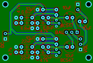
Just a hint before you read on… I have designed a PCB (Through-hole technology) for this circuit (50 by 30 millimeters, about 2 by 1.25 inches) that can be purchased via my new QRP online shop:
Visit DK7IH QRP-Shop
The method involves 2 audio tones simultaneously applied to the microphone input of the DUT (device under test). The two frequencies must not be harmonically related and must both fall within the audio passband of the transmitter. Also they should have a significant spacing in the audio spectrum. 850 Hz and 2200 Hz are a good choice, for example. If you own a spectrum analyzer with an appropriate resolution the Third Order Intermodulation products (IM3) can also be made visible. I’ll refer to that in a later page, today we want to talk about the amplitude side only.
First, here’s the circuit:
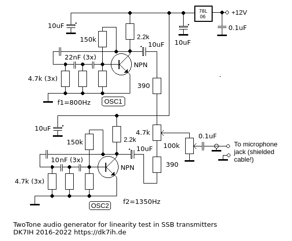
The heart of the device are two oscillators producing 2 sine waves which generate a new waveform that is formed by superposition of the 2 single signals. It resembles an amplitude modulated carrier and should look like this when displayed with an oscilloscope:
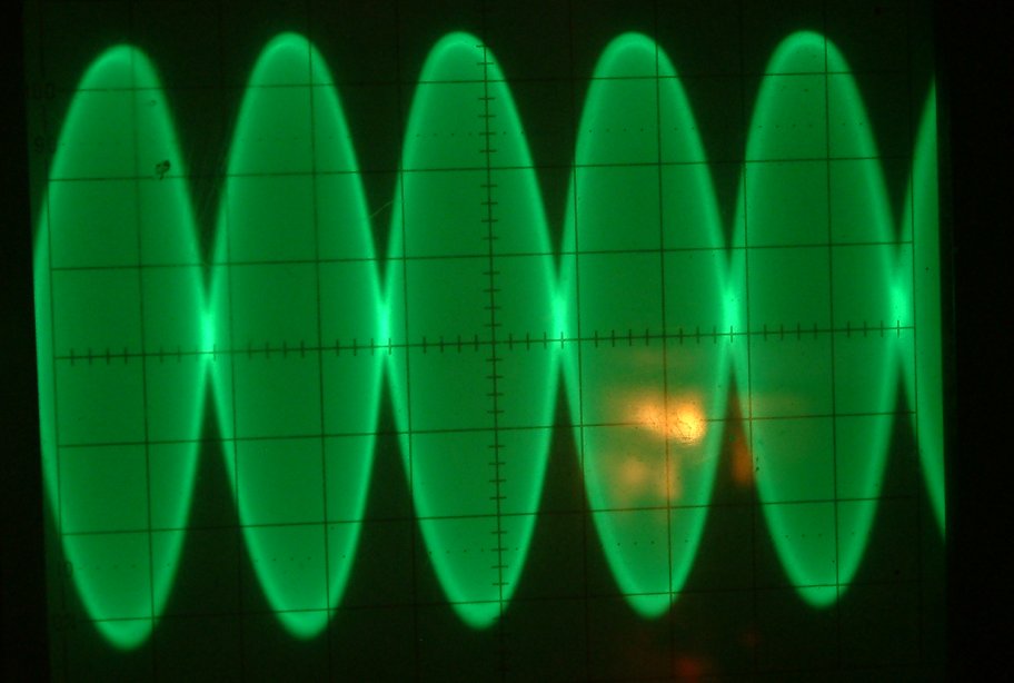
The “balance” of the tone generator circuit must be carefully adjusted to regulate the amplitudes of the two audio signals in a manner that the cross section centering the waveform is as sharp as possible. Then the two audio signals are nearly 100% equal which will result in the demonstrated signal amplitude waveform.
Wrong adjustments of the transmitter can be easily observed like the following pictures show. First one is an amplifier that is overdriven:
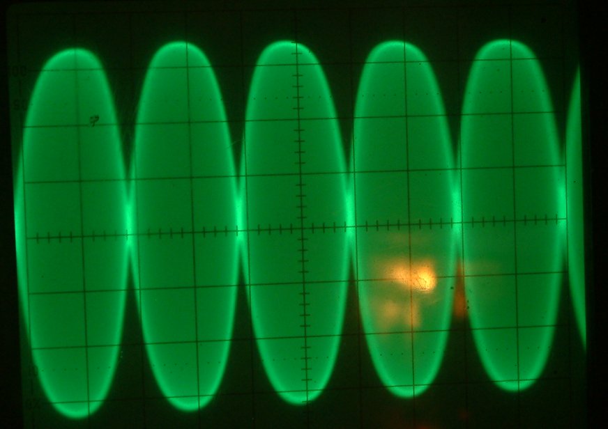
This is a sample of the classical “flat topping”. At least one amplifier stage in the exciter is running in saturated mode thus not being able to deliver proper amplification of the signal’s higher amplitudes. The transmitter will sound very distorted. Also a high set of IM3 products will appear thus make your signal much wider than acceptable.
The following picture shows an SSB amplifier running with inadequate bias setting:
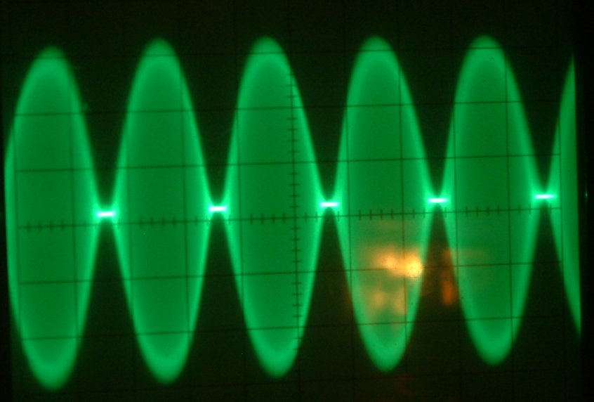
The bias in this case is much too low so that lower voltage areas of the amplitude are not amplified sufficiently. Bias setting must be increased to ensure proper amplification.
To measure the peak output of your transceiver you can either use the amplitude reading of your oscilloscope. Divide the peak-to-peak voltage by 2.81 (two times the square root of 2) to convert p.-p- voltage to effective voltage, square it and the divide the result by your 50 ohm resistive load.
Veff. = Vpp. / 2.81 (I)
P = Veff.² / R (II)
Or you use a VTVM (valve tube voltmeter) with an RF probe that gives you an RMS reading of the transmitter’s output voltage.
Keep in mind: The power you’ll get is half of the peak output power of your transmitter!
If you managed calculus, then it’s quite clear why. 😉
73 de Peter!