TESTE DE BALUN
PAGINA DE W8II
https://www.w8ji.com/balun_test.htm
Balance and need for a balun is not caused by or cured by resonance or SWR. A good match does not mean good balance or lack of common mode, nor does a bad match mean the system will have common mode or balance issues. Lack of resonance does not cause imbalance or common mode, and resonance does not prevent common mode or mitigate the need for a balun. The most common cause is improper treatment of balanced to unbalanced transitions, but common mode can come from many other causes.
Balun and Unun Testing (Important!)
SWR tests are easy but SWR tests are incomplete tests. Low SWR means a balun or unun might be good. Low SWR does not mean a system or device is good.
A balun or unun with low SWR over a very wide frequency range might not be a good balun or unun anywhere! As a matter of fact, a balun that isn't even a balun, one that always forces a system into severe common mode problems, can test perfectly on a simple SWR to load or SWR to antenna testing. A balun can still make over-the-air contacts, even when non-functional as a balun.
SWR, return loss, or input R and X with a floating resistor or antenna tell us one thing and only one thing. Floating fixed load tests only tell us input port impedance. SWR with a floating load like a floating resistor provides no meaningful indication of balun function or effectiveness. The most common way balun design mistakes get into public domain is by improper or incomplete testing.
Basic Balance Quality Test for Current Baluns
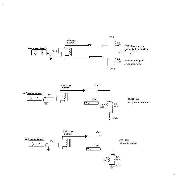
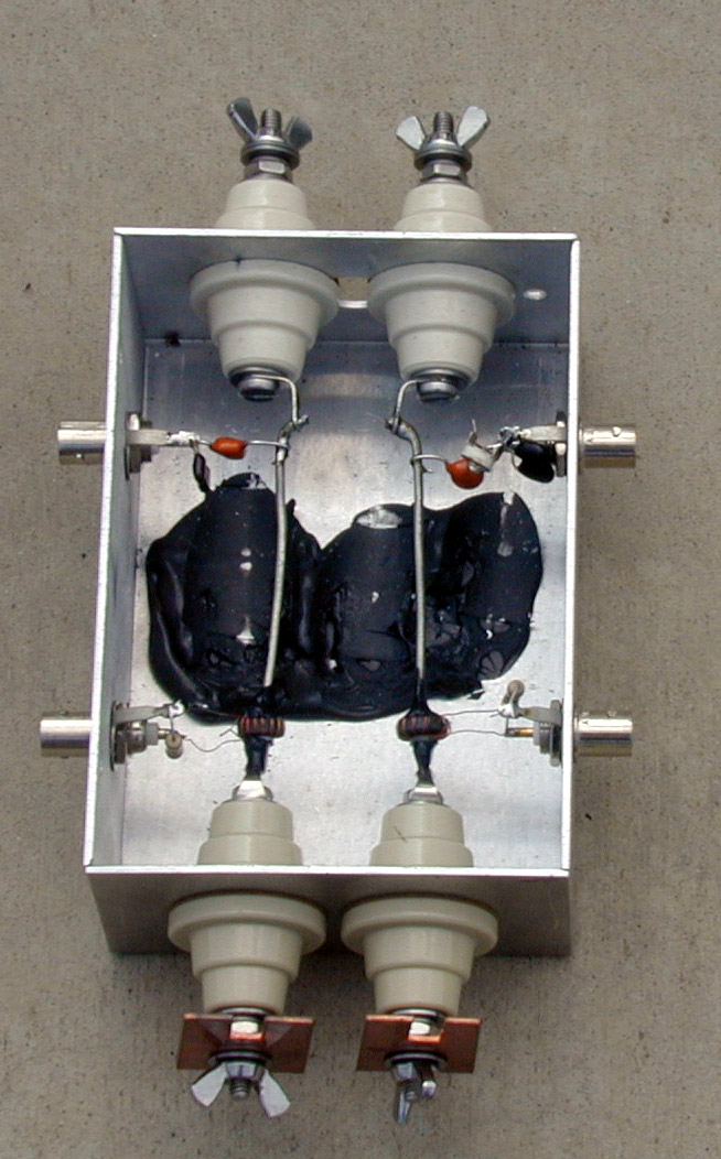
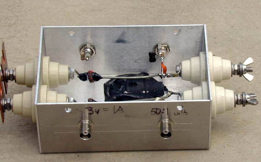
A Guanella or current balun's functional quality can be evaluated by moving a ground (common with signal source) to points Test 1, Test 2, and Test 3 (figure 1) while watching voltages or currents in the load, or even by watching input SWR. As a current balun becomes better, it will show less input SWR change as the test ground is moved between test points 1, 2, and 3. This is a very minimal test! It is the very least that should be done and still does not quantify the device for loss .
A reasonably good balun or unun will show nearly infinite input SWR when the load side is open or short circuited, and very low SWR when properly terminated. The open and short test, although crude, is important as a rough test.
A good current balun will also show very little SWR change, as the ground wire is moved from test point to test point, when terminated in the test below. It is notable that a good current or choke balun will function perfectly well as an unun or common mode isolation. An unun will normally not function as a balun, however.
The sum of R1 and R2 are selected to equal system load impedance. In the example below, R1 and R2 are for a 4:1 current balun with a 50-ohm unbalanced port and a 200-ohm balanced port (4:1 balun). The total resistance of R1 and R2 has to equal balun impedance, and R1 and R2 must be equal. This means if you test a 50 ohm 1:1 balun, R1 and R2 are each 25 ohms. Keep the leads all short!
Note: A low loss network is always bilateral, it will have the same impedance ratio in either direction. Note this is NOT always true in lossy systems! Lossy systems are not necessarily bilateral. You'll see why this is important later.
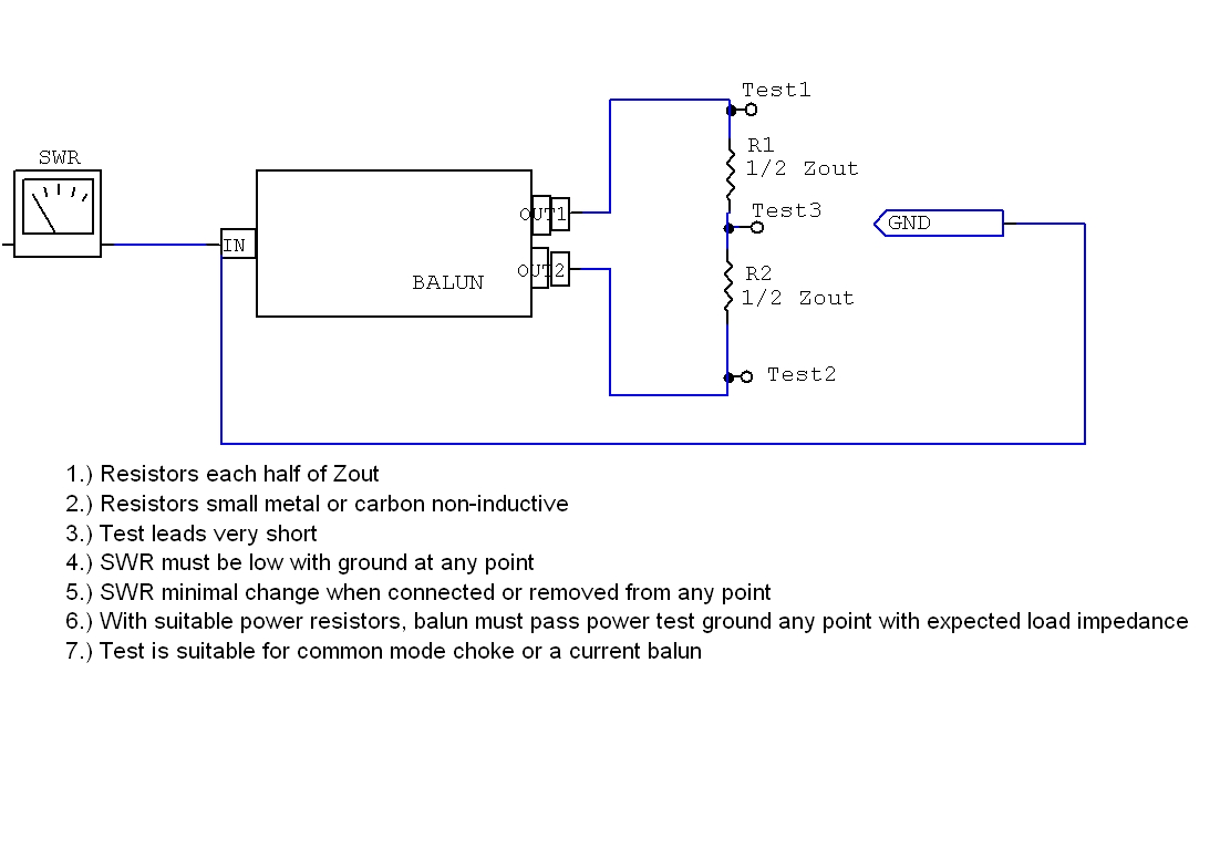
figure 1
Note: A 50 ohm balun can be tested using a pair of 25-ohm low-inductance resistors in place of the 100-ohm resistors used in the 4:1 test. In similar fashion, a 9:1 would use 225-ohm (220-ohm is perfectly good) low inductance carbon or metal resistors for R1 and R2. Leads MUST be short!
Current baluns will test with low SWR regardless of where the jumper is place. These baluns are also suitable when used as unun's or as a combination unun and common mode choke
Voltage baluns will test with low SWR when the jumper is off or when the jumper is at position B. SWR will be equally high at A or C with good voltage baluns
Unun's specific to unbalanced-only operation will test low SWR only with the ground side grounded or with no load jumper at all.
How It Works
A voltage balun will always force the two output terminals to have equal out-of-phase voltages from each output terminal to ground. This is the same as having equal impedances from each side to ground. Since impedances are equal and voltages are out-of-phase, the center tap of the resistors is an electrically zero voltage point. Grounding or floating the resistor center tap has no effect, while grounding either end (A or C) should cause a very high SWR. Similarly, both resistors could be moved to parallel connections and placed from only one terminal to ground. The SWR should be the same or very similar and the SWR should be very low with a parallel connection in a good voltage balun.
Any test of a balun or unun without doing open, short, and load on all and the balance test with the balun really does not mean much. Anything from a completely non-functional device to a nearly perfect device can pass SWR-only fixed load testing. The A,B,C wire is the very minimum acceptable with a balun, and it is a good idea to include an open and short or mistermination SWR test.
A mistermination test is made by making loads with high and low 2:1 VSWR. An example would be a 400-ohm load and a 100-ohm load test on a 200-ohm output balun, while observing input SWR. An ideal balun would show 2:1 SWR on both.
Current balun's are ground independent at the output, isolated by the common mode impedance. They can also serve as unun's and common mode chokes.
Power Testing
The same test above can be used at high power, with suitable resistors, to roughly evaluate balun power handling in ideal systems. The balun should not overheat at full power in the experimental worse case jumper position. Heating limits in an HF balun, regardless of load impedance, is almost exclusively due to losses in the core. This is true for any type of balun in the real world. Do not confuse heating with flux-saturation of magnetic materials. Flux saturation does not necessarily cause heating, it simply means the core cannot carry any more flux and any additional current causes a reduction in inductance. Virtually all HF cores heat from the loss tangent of the core. The loss tangent causes the core impedance to appear as a complex combination of resistance and reactance. The resistive part represents the dissipative characteristics, while reactance is lossless. A bench load jumper power test is much better than no test at all. This static load test does not mean the balun will work in all real world conditions!!
All baluns, even transmission line baluns, can have significant core flux under real-world loads. Many people claim heat indicates saturation, but that is not true. Heating does not indicate saturation. Core flux density and high loss tangent are the primary loss or heating mechanisms in a balun core.
See 4:1 balun page for an analysis of winding common mode currents, which can be represented by voltages across the winding.
Improved Impedance, Loss, and SWR Test Methods
Transmitting baluns and ununs should be evaluated by temperature rise. This should always be part of testing. It should be done over the entire frequency range at the widest specified load impedance range or balance range. As with the SWR test, it is possible to produced a useless result. The load has to be of the load characteristic specified or normally assumed in the device application.
For example, if we simply use a floating or one side grounded 50-ohm load to test a 1:1 balun. it is possible to have a 1:1 current balun completely pass a 5kW test, yet it can fail in 100-watt service!
We have now seen three severe shortfalls with commonly accepted tests.
- A simple load SWR test does not prove the balun or unun under test is actually working properly
- Accepting the desired power level to a test load without undue heating does not mean it is a good balun (or unun)
- Accepting power in a test condition does guarantee a device can handle that power in a real world system
Choke Impedance
This data shows the common mode impedance of the balun. In general, the highest impedance at the operating frequency or over the operating frequency range is desirable. This impedance isolates the antenna from undesired signals on the feed line shield, and prevents antenna terminal voltage from exciting the feed line with unwanted currents. Common mode impedance is directly related to the care in design and construction.
Some articles set standards for "good" common mode choke impedance. While this seems to set definitive design standards, targeting a specific minimum impedance goal is generally meaningless in the real world. Pay attention to the common mode choke page. Similar common mode impedance rules also apply to current baluns.
Pay particular attention to the impedance peak in air-core baluns. For narrower-band applications they make excellent baluns if load common mode impedance is not capacitive or the balun/choke is nearly at resonance. Air core chokes are generally acceptable over at least a 2:1 frequency range, sometimes much more. Once again suitability depends on the particular system.
Measuring Common Mode Impedance
The required common mode impedance is dependent on the exact application, and can vary from zero to a few thousand ohms.
Balun and Unun Loss Measurements
With any balun other than a 50-ohm or 75-ohm 1:1, power loss measurements are difficult. Almost any simple measurement method has serious flaws.
Measuring output terminal voltage, calculating power with E^2/R = P on the load side, creates multiple problems. Let's assume a properly calibrated Bird meter with Birds stated accuracy of 5% of full scale anywhere on the scale, set at full scale, on the input side. We have that 5% to contend with.
We also have the voltmeter tolerance, commonly a few percent, but the voltage is squared! The 5% voltage error is thus squared, and now we have to worry about load impedance error. The system also has two output terminals, while we hope the terminal voltages are 180-degrees out-of-phase we most likely are not sure of that. Oscilloscopes are out of the question, we have to use some sort of accurate vector voltmeter or calibrated selective level meter.
Probably the best inexpensive home measurement technique would be using back-to-back identical devices. We can convert up to the high impedance in one balun or unun and back again in an identical reverse connected unit. This method has clear advantages, but also has some disadvantages.
For advantages, the back-to-back system allows use of 50-ohm meters at each end, or S21 and S12 measurements with network analyzers, for loss and mismatch errors.
Taking half the measured loss through two identical devices can get us very close to the real loss **if** both the baluns and ununs are reasonably low loss and the baluns are properly balanced. As the loss goes up, measurement errors also increase above basic calibration errors.
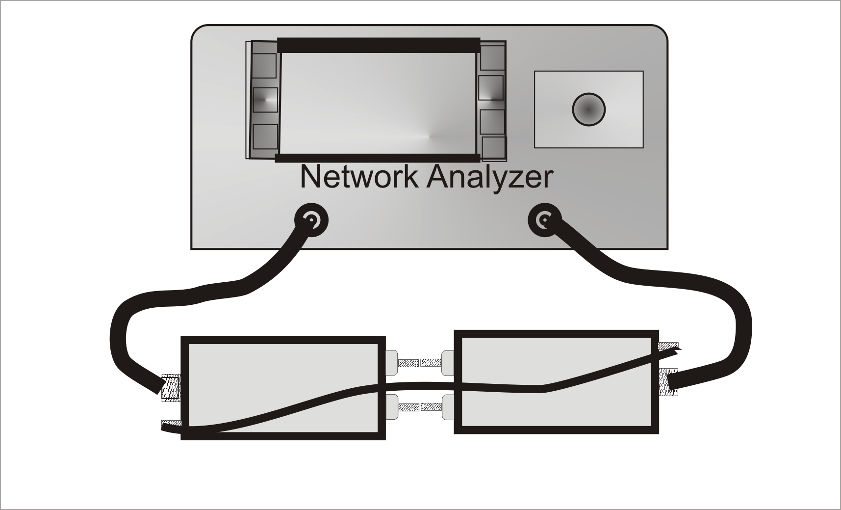
Transmission loss through a device, as in the test above, may not give the exact power loss. It is, however, close enough to spot any significant problems. It is infinitely better than no measurement at all. .
(being edited 2/12/2019)
Measured Impedance
Common-mode impedance varies with frequency, as the following Smith Chart common mode impedance plot shows:
Unless the winding style and physical size places unwanted series resonances outside desired bands, an air-core balun is generally good for a maximum frequency range of three or four-to-one. An air core choke is generally useful when common mode impedance is inductive or the common mode system impedance has same sign as the choke or balun's common mode impedance. If we are not careful with system design, an air-core balun can make system balance worse!
In contrast a good core-type balun looks like this:
SWR
The lowest SWR is desirable, although any mismatch can often be compensated by adjustment of antenna dimensions. This SWR mainly comes from incorrect wire impedance inside the balun. It may be caused by excessive length of internal leads, or incorrect cable or winding impedance inside the balun. It generally is a construction related problem.
Measured SWR and Choking Impedance
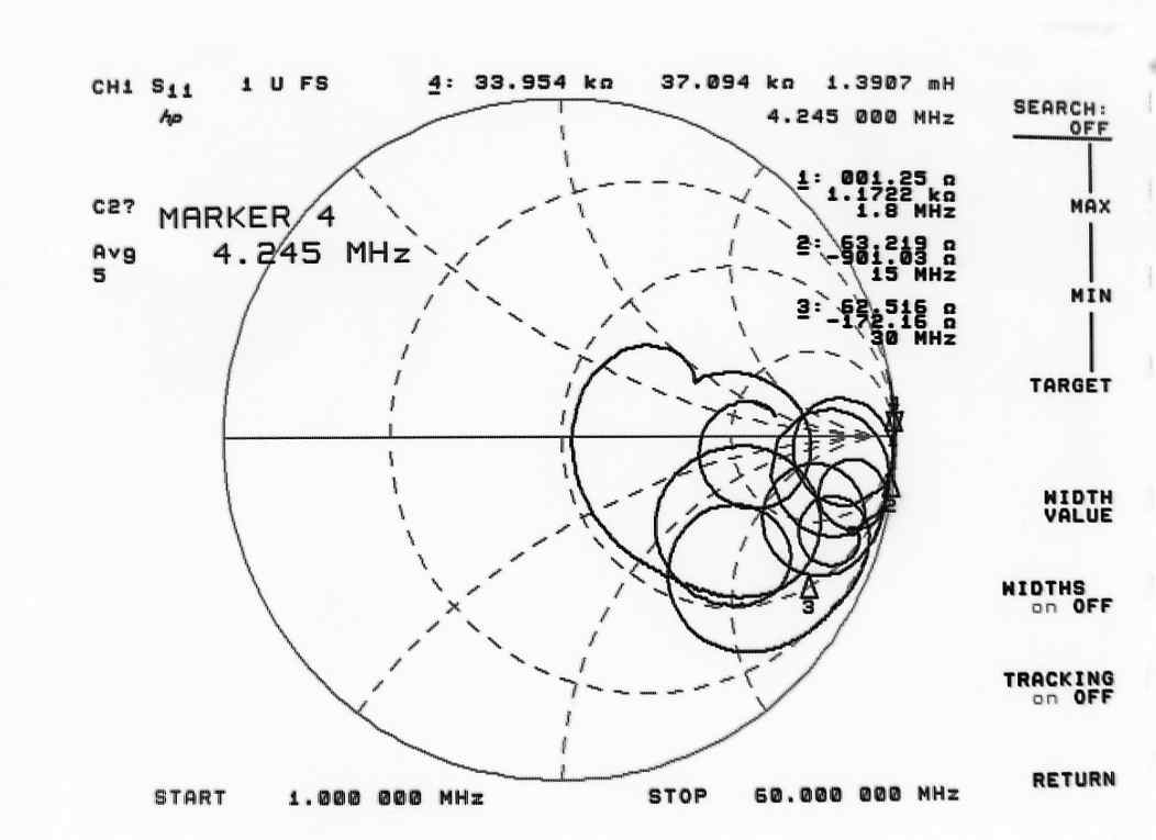
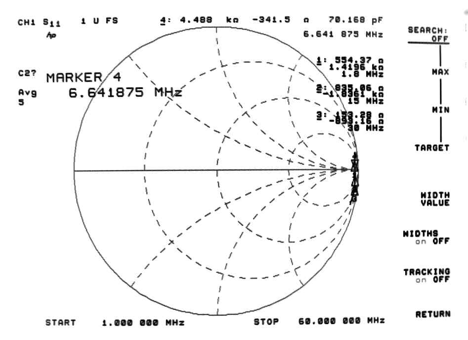
The following data is measured using a currently certified network analyzer with low capacitance test fixture:
| Centaur | DXE | W2DU(1) | W2DU(2) | Force 12 | Scramble | Solenoid | W2AU volt | ||
| Choke Impedance | Note 2 | ||||||||
| R+X@1.8 | 84 129j | 554 1.4k j | 378 617j | 230 325j | 169 286j | 1.67 245j | 1 +1.18k j | .488 5j | |
| R+X@15 | 3.76 2.7k j | 835 -1.84k j | 727 -611j | 761 -10j | 883 -105j | 11.97 -850j | 62 -895j | 1.36 42j | |
| R+X@30 | 143 -729j | 153 -893j | 284 -440j | 610 -296j | 538 -381j | 73 162j | 68 -168j | 8.2 68j | |
| Max Z@F | 17 MHz | 6.65 MHz | 7.16 MHz | 15.3 MHz | 13.24 MHz | 6.42MHz | 4.25 MHz | 60 MHz | |
| R+X at max Z | 5.87k -943j | 4.5K -340j | 1.3K -13j | 770 -20j | 914 2.25j | 42.7k 0j | 34K 37K j | 75 286j | |
| Min Z@F | 27.68MHz | 11.7Mhz | |||||||
| R+X at min Z | 10 -2j | 198 -252j | |||||||
| SWR | |||||||||
| F SWR=1.25 | 6.8 MHz | 65 MHz | 21.15 MHz | 20.2 MHz | note 1 | note 1 | 20.9 MHz | ||
| 1.8MHz | 1.07 | 1.02 | 1.03 | 1.03 | 1.43 | ||||
| 15MHz | 1.58 | 1.04 | 1.17 | 1.18 | 1.2 | ||||
| 30MHz | 2.16 | 1.08 | 1.37 | 1.39 | 1.35 | ||||
note 1: SWR not measured because construction and cable type affects SWR
note 2: This is a W2AU voltage balun. It is only shown as a example of poor shield isolation offered by voltage baluns if the antenna is not perfectly matched to the balun with the feed line exiting the balun at right angles. This type of balun is unsuitable for non-symmetrical systems such as off-center-fed antennas, verticals, or antennas with the feed line paralleling the antenna (even at a fairly large distance).
The W2DU baluns were manufactured by Unidilla. (1) is a Maxi balun and 2 is a 10-40 meter model.
The DX Engineering balun is the dipole balun type DXE-BAL050-H05-P
The scramble-wound choke was about 20 feet of RG8X in a six-inch diameter "bundle".
The solenoid balun was about 60 feet of RG-8X on a 4" PVC thin wall drain pipe coated with rubberized roofing tar.
Power Dissipation and feed line Common-mode Current Estimates
Note: This section revised 1/2/2003 to correct model error. Please report any other errors to me!
Balun power dissipation is estimated using Eznec to simulate a perfectly balanced dipole.
Here is a copy of the model used:
Please be aware I made no special effort to create a "bad antenna" other than I intuitively understand what the worse case condition of feed line length would normally be and I selected that length. I dropped the wire representing the feed line vertically from the center of a perfectly balanced dipole, and made that wire 1/4 wl long.
Here is a view of the model with no balun:
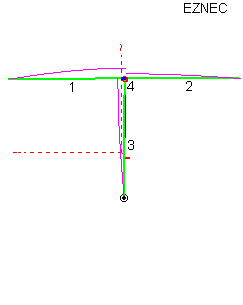
SWR is 1.46:1 power is 1500 watts
Currents at 1500 watts are approximately:
5.65 amperes into wire 1
2.63 amperes into wire 2
3.73 amperes into wire 3 (coaxial cable shield)
Using this model (a 135 foot high 160-meter dipole) we can add each of the balun impedances in the coaxial cable shield and estimate feed line current and power dissipated in the balun:
| Centaur | DXE | W2DU(1) | W2DU(2) | Force 12 | Scramble | Solenoid | W2AU |
| 0.90 amp | 0.12 amp | .25 amp | .47 amps | .57 amps | .87 amps | .16 amp | .4 amps |
| 69 watts | 8.5 watts | 25 watts | 51 watts | 55 watts | 1.3 watts (26w TL loss) | .03 watt (74w TL loss) | 34 watts |
From this we can see the following:
- Adding more beads is very inefficient. W2DU(1) has about twice the beads as W2DU(2), yet it has 53% of the current and 49% of the power dissipation! This does increase power rating by a factor of four, but it is still too low to prevent balun heating.
- The solenoid has (by far) the lowest choking or balancing power loss, but it is 60-feet of RG-8X wound on a 4" diameter form in a single layer. It adds transmission line loss of 74 watts, but since the area is so large it will not overheat.
- The scramble wound balun has inadequate impedance since wire length is only 20 feet. It has low loss, but it really isn't acting like a balun (at 6.5 MHz it would be super, having 42K ohms of impedance).
- Of the baluns above, only the DXE, scramble wound, and solenoid would not be overheated in normal operation for continuous Morse CW transmissions.
Perspective of Heat
Think about the heating this way. Imagine you had a 60-watt light bulb. Nearly all of the applied power is turned to heat, and the surface area of the bulb and conduction through the base radiates that heat. Would you hold a 60 watt light bulb?
Now picture a balun core with a surface area a fraction of the size of the light bulb. This core area is enclosed in a case that often has poor thermal conductivity.
- The large air-core baluns mainly produce heat from transmission line losses.
- W2DU and other style baluns mainly have CORE losses. Transmission line losses are negligible since the transmission lines are very short.
Currents
Every ampere of current not going onto the cable shield goes to the dipole's shield-fed leg! The total is not the exact sum, because of phase differences. Here is a view of currents in the dipole with the DXE balun:
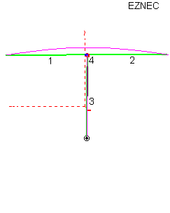
Currents are:
Wire 1 4.52 amperes
Wire 2 4.52 amperes
Wire 3 .12 ampere
Remember power radiated increases by the square of current. The feed line shield current is now .12A compared to 3.73A without a balun! The feed line radiates about .1% of the power it radiated without a balun. While pattern distortion on transmit may not hurt, the feed line radiation probably aggravates RFI and allows noise to couple into the antenna when receiving.
Remember this model is worse case in the NO BALUN condition. This does not mean every system or most systems will be this bad. This example was only intended to show how bad balance can be and how much power baluns (even with a matched load) can dissipate!
Ladder Line Voltage and Current tests
The data below was taken with a half-wave 80 meter doublet about 120 feet or so above ground. This doublet is suspended between two towers and is suspended by rope for at least 30 feet from each tower. Nothing is within 100 feet of the doublet. feed line is a vertical drop of Wireman "heavy duty" ladder line, twisted to maintain electrical balance and reduce wind oscillation.
In the table below, "D C" is a standard dual-core two-transmission line balun. It has two independent magnetic paths for each balun transmission line.
Look at how terrible balance is on a single-core 4:1 "current balun" below. A 4:1 single-core "current balun", as presented in "Baluns and Unun's" and used in some commercial designs, forces a system into gross voltage unbalance. It is not a balun. This is what happens when we offer a balun design without understanding or measuring balance.
www/images/Baluns/XLS/balun5m.xls