QFH ANTENA 137MHz SATELITE METEOROLOGICO
BATEDOR DE OVOS
http://jcoppens.com/ant/qfh/calc.en.php
Home
Antennas
QFH
Calculator
Antennas
QFH
Calculator
QFH
Introduction
Matching
Calculator
Simulations
Dimensions
Groundplane
Related:
Simple helicoidal
_______________________________________________________________________
ANTENA QFH
consulta ao site do Mestre Roland Zumerli PY4ZBZ
MAIO DE 2023
trabalho no cefet rj sobre recepcao de satelites meteorologicos em 137MHz
montagem da antena qfh de tubos de cobre 9mm (3/8")

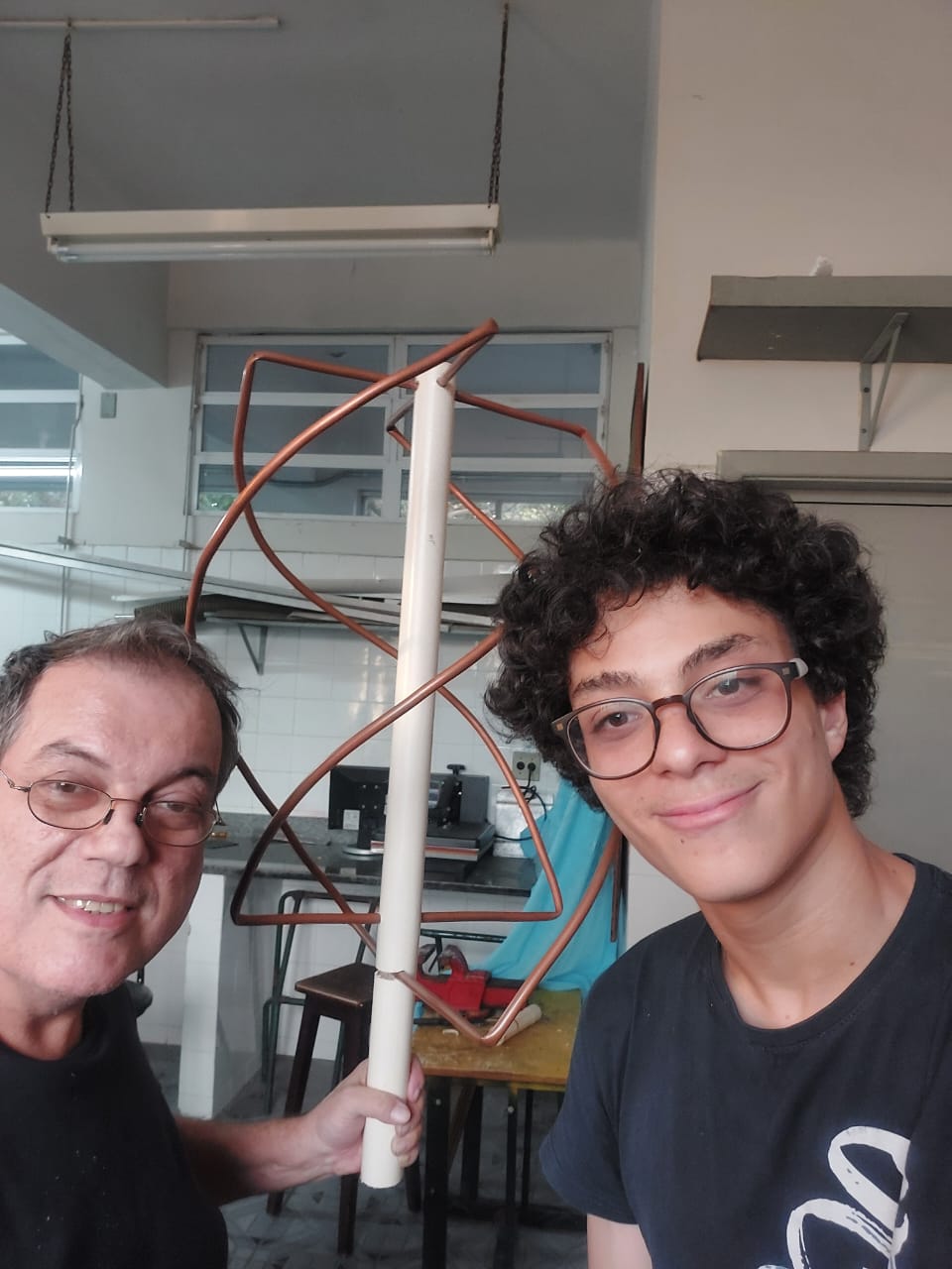

Sandro Almeida 2B ELT 2023, Gabriel Dourado 2B ELT 2023, Omar 3B ELT 2023 e eu, Aridio.
________________________________________________________________________
http://www.g4ilo.com/qfh.html
A QFH antenna for the weather satellite band


________________________________________________________________________
CALCULO DA ANTENA QFH
Legend
This calculator generates a lot of data! Take care in the use of the information in order not to make mistakes...Here's a little explanation:
- Design frequency
- Evident?
- Number of turns (twist)
- What's the twist of the antenna? (normally 0.5 (180 degrees)
- Length of one turn
- A few variations of the antenna exist. Normally the circumference (length of the loop) is 1 wavelength, but 1.5 wavelength and 2 wavelength versions exist.
- Bending diameter
- As it's impossible to bend the corner abruptly at 90 degrees, this value is needed for the calculations. It's measured from the bending center to the center of the tube.
- Conductor diameter
- External diameter of the tube or coax cable.
- Diameter/height ratio
- Most frequently this ratio is 0.44, but slightly lower values (0.3 to 0.4) give better horizon coverage.
- Wavelength
- Wavelength, corresponding to the selected frequency.
- Compensated wavelength
- Wavelength, compensated according to the conductor diameter.
- Bending correction
- Correction value needed according to the bending diameter.
- Total length
- Total length of the loop, before compensation.
- Total loop cmpensated length
- Total length of the loop, compensated for the bending effect, and the fact that the loop must be slightly larger (or smaller). This is the amount of tubing necessary for this loop.
- Compensated vertical separation
- Vertical separation (without the 'bends').
- Compensated horizontal separation
- This is in fact the horizontal part without the 'bends', and corresponds to the horizontal pipe necessary to support the cable.
- Antenna height
- Height of the loop (twisted!).
- Internal diameter
- The diameter of the (imaginary) cylinder on which the loop would be wound.
| (c) John Coppens ON6JC/LW3HAZ |