thoughts on Delta Loop (or Triangle Antenna or Simple Multiband Antenna
or HF Delta Antenna)”
Yuri, UB6AFC
I have been suffering with a
similar antenna, for almost a year now. Of course, not every day, but if you
count, then two months out of the year. I read on the Internet about the
excellent results of the Delta 80m band. I fight with it this way and that, but
achieve the desired SWR, I made it from a thick field P-268 into one core. The
wire is strong, light and relatively cheap. an equilateral triangle in the
private sector, the mast is one -15m. The angle turned out to be about 45, as
recommended. 3.680 MHz. SWR 1.8 resistance 86 ohm. I built a quarter-wave
transformer from a 75 ohm cable 13.90 m long. Resonance 3.730 SWR-1.56
resistance 51 ohm, reactance + 32. good passing! Can anyone help? Has anyone
already gone through this? I would be very grateful. Yuri, UB6AFC / 73 !!!
RK3DBU Post author
Hello UB6AFC!
Many people suffer all their lives with the antenna and do not get the
desired result, so the year is flowers 🙂
For me, the result you described is quite good, SWR 1.8 for a multi-band
HF antenna is normal.
As a next step, I would try to replace the quarter-wave transformer with
a balun on ferrite rings, I liked this solution more!
Good luck to you!
Kuldybek
It is better to feed the vertical Delta loop antenna from the lower
angle using 1/4 wave two-wire line as advised by EW8AU. At the same time, it is
easier to coordinate with the PK-50 or PK-75 cable of any length. The
polarization is vertical, there is also radiation in the horizontal plane.
Initially, the antenna must be tuned to the resonance frequency using a line
(PK-50/75 cable) of a multiple half-wave with Ku. And then just turn on the
two-wire line. Look for the cable switch-on point by moving the cable along the
two-wire line along the SWR minimum. With this matching, it is very easy to achieve
SWR-1. This is easier than using any transformers or looking for where R.in.
antenna under the R. power cable. Proven in practice. The antenna works great.
Good luck to everyone and 73! BEC. UN7TX.
Kuldybek
Good afternoon everyone. A
simple option for matching a single-band vertical Delta loop antenna was
proposed by EW8AU using a two-wire quarter-wave lily. At the same time, you
don’t need to look for where the R.in. turn on the two-wire line and look for
the matching point with the cable by moving the cable along the line. A simple
way to match and you can always achieve accurate matching of the antenna with
the PK-50 or PK-75 cable. Powering the antenna from the bottom corner. No need
to fool around with all sorts of transformers, etc. The height of the antenna
suspension does not matter, since the matching can be corrected. It works with
vertical polarization, it also has a small radiation with horizontal
polarization. It has been tested in practice. Good luck to everyone. 73!
BEC.UN7TX
Refers to loop (frame) antennas, as well as squares. The perimeter of
the antenna is approximately equal to the wavelength. Applies to all HF bands.
The designs mainly differ in the antenna suspension and feed point. The
efficiency of the antenna is directly related to the area (a circle is ideal,
but it is difficult to achieve), so an isosceles triangle will be preferable.
However, any form of antenna is allowed depending on the specific conditions.
On the low-frequency ranges, “lazy deltas” (i.e., suspended almost
horizontally) are mainly used, and on the high-frequency ranges, vertical or
inclined “deltas” are mainly used. Low-frequency "deltas" operate on
multiple ranges due to excitation on harmonics. At the same time, the main
radiation of the horizontal deltas at the “main” lower frequency is directed
upwards, which is not very favorable for DX. But at higher harmonics, the
petals of the diagram are pressed to the ground.
However, the properties of the "delta" are highly dependent on
the specific placement and design (especially low-frequency ones), so they have
a lot of conflicting reviews.
vertical deltas
The best place for the DX to feed on the delta is at the bottom corner.
However, when the antenna is placed low at an upward angle, it is better to
feed through the side corners. In this case, there is more radiation with
vertical polarization.
Vertical delta compares favorably with dipole and GP. Compared to a
dipole at the same height, a vertical delta has most of the radiation at a low
angle to the horizon. Compared to the “verticals”, the delta is easier to
manufacture, because. no complex system of counterweights is required.


The input impedance of the antenna depends on the feed point and ranges
from 60-300 ohms. With a high input impedance, power is supplied through a
matching transformer. Single-band antennas can be powered through a
quarter-wave transformer (Q-matching), a quarter-wave segment of a 75-ohm cable
is included between the antenna and the 50-ohm cable.
Horizontal deltas
In fact, it is square, turned into a triangle. You have to pay for
saving braces with less efficiency, because. antenna area is smaller.
The 80m horizontal (lazy) delta is quite popular. It is often installed
between multi-storey buildings. At 80 m, the radiation pattern is a pea, i.e.
the main radiation is directed upwards. Such an antenna can be excited at even
harmonics, i.e. 40, 20 and 10 m. Moreover, with increasing frequency, the lobes
of the radiation pattern are pressed to the ground.
One of the main problems when setting up such an antenna is the choice
of a feed point and coordination with the feeder. Most often, a broadband
transformer is used as a matching device. However, it should be noted that the
input impedance of the delta is highly dependent on both the power point and
the location in space.
On the Internet forums for the formation of radiation with vertical
polarization, the supply of the "delta" to the "lower"
(from the ground) angle is mainly discussed.

or at a distance L / 4 from the "lower" point B, i.e. near the
ground.

In Figures 1 and 2, at points B and D, the antinode of the current, at
points A and C - the antinode of the voltage.
I immediately rejected such an antenna solution: the antenna is already
installed low, and with such power supply, the main radiation occurs near the
ground. In addition, the antenna should be powered as shown in Fig. 2 only from
the 9th floor - after all, no one has canceled the desirability of placing the
cable perpendicular to the antenna canvas, and it would be nice if the radio
station was on the 9th floor.
It is known that the highest intensity of electromagnetic radiation is
located near the antinode of the current: "the radiation power of a
segment of the antenna wire is proportional to the square of the current in
this segment", i.e. the radiation power in each segment of the antenna
wire is different, the maximum is in the antinode of the current.
For the antenna shown in Fig. 1, the current antinode at point B is at
the very bottom, and for the antenna in Fig. 2 it is slightly above the bottom
of the antenna, which is not so bad. However, for a low-hanging delta, this
option is not suitable either.
Based on these considerations, I decided to make an antenna with power
supply in the upper part at a distance L / 4 from the upper point B (Fig. 3).
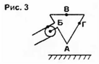
In fact, this is an "inverted" antenna, shown in Figure 2.
Figure 3 clearly shows that the antinodes of the current (points B and
D) are located at a higher height, which means that the radiation maximum
occurs quite far from
ground, which is very important when the antenna height is low. In
addition, this configuration facilitates an almost perpendicular cable entry to
the antenna web.
With a 10-meter suspension height of the upper canvas, a good dual-band
(40 and 20 m) antenna was obtained, installed
at an angle, because it is impossible to make it completely vertical at
such a suspension height. The lowest point of the antenna is literally a meter
from the ground, but this has practically no effect on the radiation
efficiency.
It should be noted here that the locations of the current and voltage
antinodes indicated in Fig. 1-3 are valid for the 40 m range antenna. In the 20
m range, 2 waves fit in the antenna, current and voltage antinodes will be 4
each, so you get complex polarization - vertically -horizontal.
The antenna sheet is made of copper wire with a diameter of 2 mm in
enamel insulation. The delta is an equilateral triangle with sides of 14.34 m,
the perimeter is 43.02 m. The distances between points A, B, C and D (Fig. 3)
are equal and equal to 10.75 m. angle - 3.58 m. With such dimensions, the
resonant frequencies of the antenna are 7040 and 14100 kHz, the antinodes of
the current B and D are opposite.
If these proportions are observed, in some directions the antenna may
have a certain gain. If necessary, it is convenient to shorten the lower
corner, reducing the length of 3.58 m, for example, to 3.50 m. A slight
inaccuracy in the location of points B and G horizontally does not lead to a
noticeable deterioration in antenna performance.
The balun at the feed point had to be abandoned, because. it is subject
to wind loads. Therefore, at the power point, instead of a heavy balun, 5
RF-130S ferrite "latches" are installed on the cable. For the same
reason, it was necessary to abandon any coordination in the power supply unit.
The shield of the cable is connected to the top of the antenna, the center wire
to the bottom.
The most relevant characteristics of the antenna (impedance and SWR)
were taken by the AA-ZZOM analyzer using a half-wave repeater made of a 50-ohm
coaxial cable 14 m long. In the 7 MHz band, the active input impedance was 120
Ohm, in the 14 MHz band - 140 Ohm . Due to the insufficient height of the
suspension, there is a reactive component of the input impedance, therefore, in
the range of 7 MHz, SWR = 3.0; in the range of 14 MHz - 4.0.
In such a situation, it was decided to reduce the SWR by using a
matching segment of a 75-ohm cable. Combining the connection of short sections
of such a cable with a length of 10 cm, 20 cm, 30 cm, 50 cm, 1 m, 2 m, 3 m, 3.5
m equipped with cheap television connectors, after a half-wave repeater it
turned out that in the 7 MHz band a cable length of 6 .9 m, in the range of 14
MHz - 3.5 m, which made it possible to obtain SWR = 1.2 in the range of 7 MHz;
in the range of 14 MHz - 1.5.
As a result, it was decided to connect a segment of a 75-ohm cable 3.5 m
long directly to the antenna, and already to it - a 50-ohm cable 8.6 m long (14.1
m in total). Unfortunately, due to the inaccurate choice of the length of the
half-wave follower (it was determined by calculation), in the 7 MHz band, the
SWR was 2.0; in the range of 14 MHz - 2.3. This is not so bad - with SWR up to
3.0, all the power goes into the antenna. Moreover, an increased SWR is
available only in a cable 14 m long.
The cables are 10 mm in diameter and have a stranded center conductor. A
plastic elbow about 15 cm long, cut to the diameter of the cables, is attached
to the junction of the cables, which ensures the reliability of the connection
under wind loads.
At the bottom, nothing prevents the installation of a current balun
equipped with connectors, which will finally cut off possible common-mode
currents.

In fact, the SU at 7 MHz can operate in the ranges from 1.8 to 15 MHz.
The 14 MHz control system uses a 6 mm diameter copper tube coil (1+2+4+4 turns,
11 turns in total) and can be used in the 7-29 MHz bands.
If instead of the last 4 turns, wind 8 (there will be 15 turns in
total), then, in principle, the control system will work starting from 3.5 MHz,
and possibly from 1.8 MHz (should be checked in practice). Due to the ease of
manufacture, I made 3 such SUs. As a result, after the matching devices, the
frequency band without the reactive component was 400 kHz on the 40-meter band
and 380 kHz on the 20-meter band.
This matching was done in order to reduce the losses in the 50-meter
coaxial cable as much as possible, which is connected to the second antenna
switch. There are 20 ferrite "latches" installed in two places on
this cable. The SWR in a long cable connected to the output of the matching
device is about one. Matching devices on lumped elements can be completely
replaced with additional segments of a 75-ohm cable, the lengths of which will
have to be selected.
The antenna can be simplified if it works on one band. In this
embodiment, the length of the 75-ohm cable segment connected to the antenna web
is 3.5 m in the 14 MHz band and about 7 m in the 7 MHz band. The matching
device can be installed in the radio station or do without it.
There is another option: power the antenna only with a 75-ohm cable (for
example, PK75-4-11). This is how it was used in the field with a half-wave
repeater (about 28 m) and a 9-band switch. In September 2013, Sergey, RW9UTK,
and I worked in the field from a relatively rare KE-21 RDA region. The antenna
operated on two bands and was mounted at a height of 12 meters on two
fiberglass pipes. The antenna worked perfectly - at other times we learned what
a pile-up is.
There, in the field, the AA-33OM analyzer measured some characteristics
of the antenna, which, due to the higher suspension, turned out to be
noticeably better than the antenna installed at a 10-meter height. In the 40m
range, there was no reactive component at all, Rin = 141 Ohm, SWR = 1.91, band
in terms of SWR = 2.0 - 80 kHz, in terms of SWR = 3.0 - 300 kHz, active
resistance remains in the band 800 ( !) kHz. In the range of 20 m, the reactive
component was also absent, Rin = 194 Ohm, SWR = 2.56, the band according to the
SWR level = 3 - 620 (!) kHz, the active resistance is stored in the band of 630
(!) kHz.
Coordination was carried out using a self-made control system, to which
a 75-ohm cable was connected. The use of a matching device made it possible to
obtain SWR = 1.0 on both ranges in a 50-ohm cable connecting the control system
with the transceiver.
A wide band of operating frequencies without reactance is a remarkable
property of closed antennas. There is no need to rebuild the control system
within the amateur range - it is enough to adjust it at one point. In this
case, the SU can be quite far from the transceiver.
In the field, we used the P-274 field double wire as an antenna sheet.
This wire in polyethylene insulation has a certain shortening factor, so the
perimeter of the antenna turned out to be somewhat smaller, despite the greater
suspension height than at home, and amounted to 42.70 m.
There was also an equilateral triangle with a side of 14.23 m. The
distances between points A, B, C and D are also equal and are 10.67 m each. The
distance from the power supply unit to the upper corner is 3.56 m.
Some problems arose with the balun, which is part of the universal line:
plastic circles from the pyramid toy were used to move the antenna web, and the
balun slightly shifted down from the projected point (3.56 m from the top).
Despite this, the antenna worked just fine, because. on 12-meter pipes, it was
installed almost vertically.
It is planned to move the balun to the beginning of the line, providing
it with connectors. to maintain protection against common mode currents. In
addition, ferrite “latches” can be put on a cable lying on the grass or passed
several times through a ferrite ring - a cable with a diameter of 7 mm allows
this.
It is also planned to test the antenna in the field, but already at a
height of 16 m, fiberglass masts will be used again. The antenna will be
installed vertically. I'll let you know the test results.